
Orifice Flange
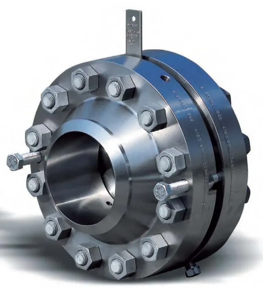
Weld-neck and slip-on orifice flanges with integral pressure taps, 2" to 24" in ASME Class 300 to 2500, supplied as matched pairs with jack screws, plugs, studs and nuts. The standard mounting for orifice plates in liquid, gas and steam service.
Orifice Flange
An orifice flange assembly is the pipe-mounted housing for an orifice plate. Each flange of the pair carries a tapped hole located precisely one inch from the plate face, so the differential pressure is taken at the standardised flange-tap position defined in ISO 5167 and ISA RP3.2. Jack screws in the flanges spread the joint so the plate can be exchanged without removing the pipe section.
Flanges are available as weld-neck or slip-on, with raised-face or ring-type-joint facing, in sizes from 2" to 24" and ASME Class 300 to 2500. Process temperatures range from −169 to +850 °C depending on the material, which can be 304, 316 or 316L stainless steel, Hastelloy or Monel to match the pipeline specification. Each set is delivered with two plugs, two jack screws, ASTM A193 B7 stud bolts and A194 2H nuts, with gaskets on request.
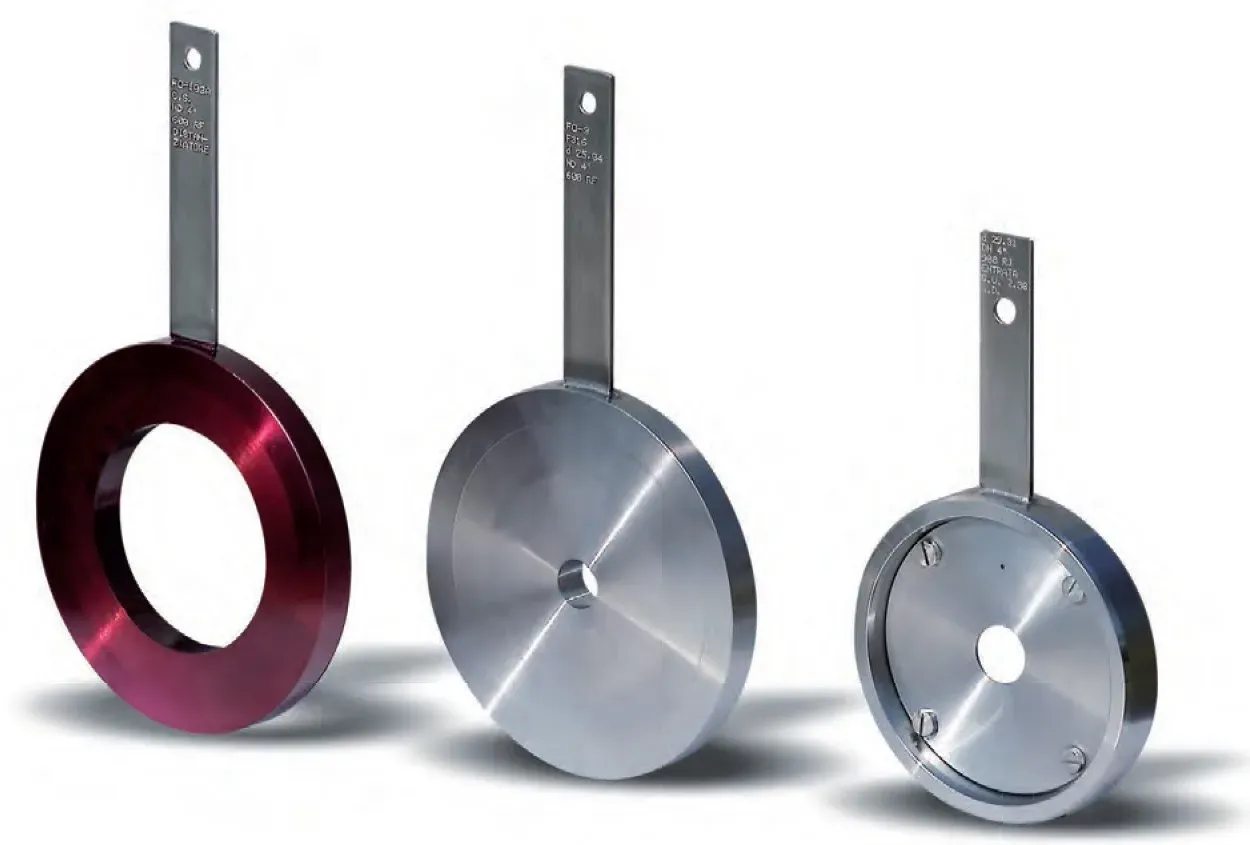
The output is the differential pressure across the plate, taken to a DP transmitter or gauge through a manifold. Because the bore of the plate is calculated per application, the flange set is normally ordered together with the orifice plate and, for full traceability, with the flow calculation sheet.
Orifice flanges are used wherever DP flow measurement is specified for liquids, gases and steam: oil and gas, petrochemical, chemical, power generation and water plants.
Flow
Spec it with our engineers
Send us your process conditions and we’ll recommend the right configuration — with a quote inside one business day.