
Multi-Stage Orifice
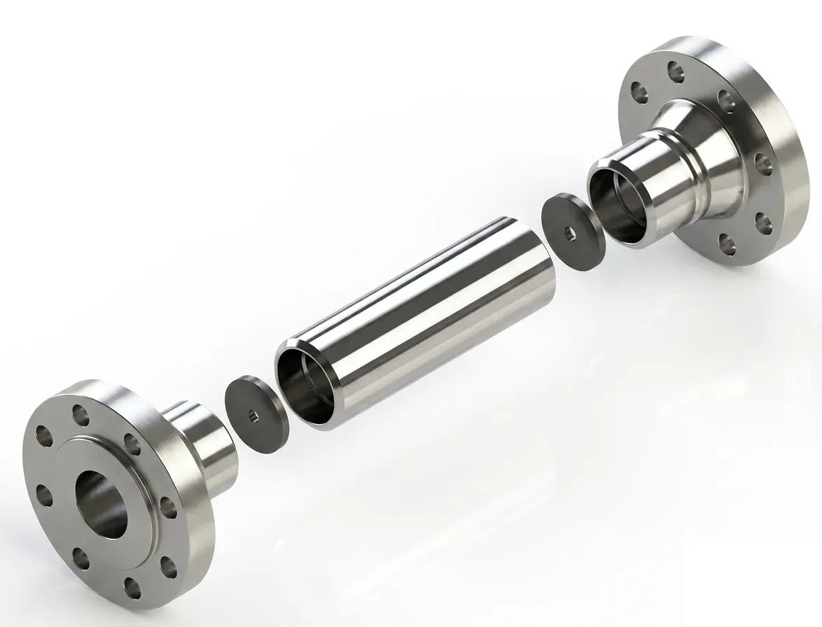
A stack of calibrated orifice plates that reduces a high pressure differential in several controlled steps instead of one. Sizes ¾" to 10", ASME Class 150 to 2500, flanged, socket-weld or butt-weld, with optional taps to monitor each stage.
Multi-Stage Orifice
A multi-stage orifice is a restriction device, not a flow meter. When a large pressure drop has to be taken across a single orifice, the fluid velocity in the vena contracta rises far enough to cause cavitation in liquids, choked flow and high noise in gases, and erosion of the plate and downstream pipe. Splitting the drop across several calibrated orifices in series keeps the velocity and the pressure ratio at each stage within safe limits.
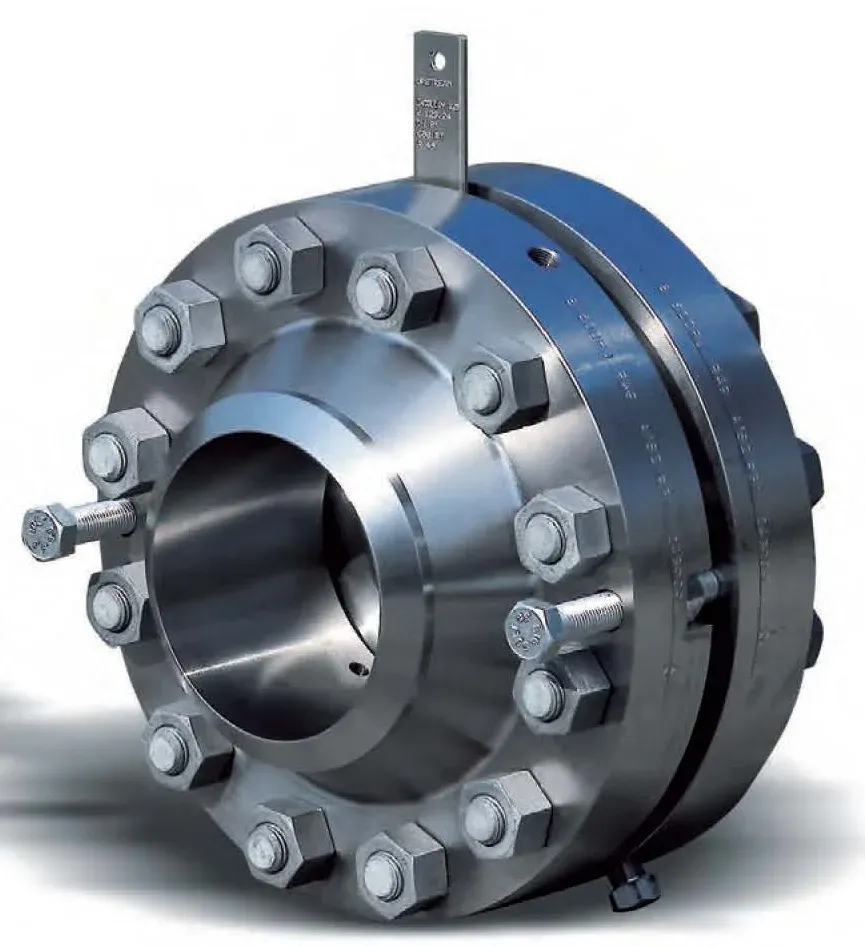
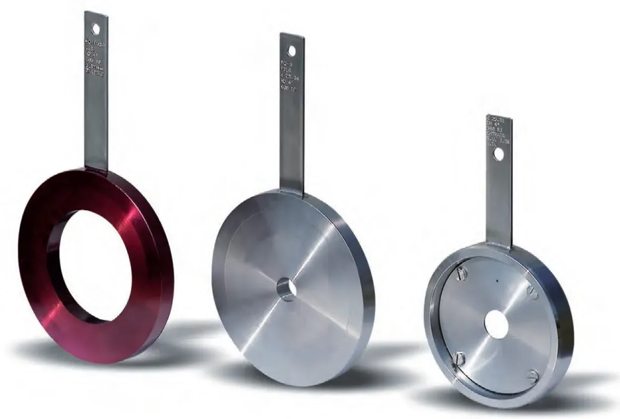
Each stage is an AISI 316 plate with a bore engineered for its share of the total drop; the body and flanges are selected to match the pipeline material. Sizes range from ¾" to 10" with flanged (RF or RTJ), socket-weld or butt-weld connections in ASME Class 150 to 2500. Optional pressure taps between stages allow the pressure profile to be verified during commissioning.
Typical duties are letdown lines from high-pressure separators, minimum-flow recirculation on pumps, blowdown and drain lines, gas pressure reduction to flare and compressor anti-surge bypass, anywhere a control valve is not needed but a single orifice would be destroyed.
Every unit is engineered for the stated flow, inlet and outlet pressure and fluid properties, and delivered with the calculation. Users are oil and gas, petrochemical, chemical and power generation.
Flow
Spec it with our engineers
Send us your process conditions and we’ll recommend the right configuration — with a quote inside one business day.